

The setup
A team in China was stuck.
They were running fully-automated hand-eye calibration — solving for the 4×4 rigid transform between a robot’s end-effector frame and the camera’s frame. Every industrial vision project that puts a camera near a robot has to do this. Get this wrong, and nothing downstream works.
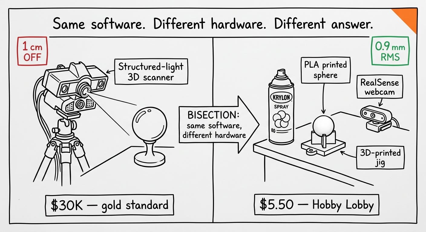
Their setup was textbook: a structured-light 3D scanner plus a precision ceramic calibration ball with 0.5-micron surface tolerance. The “gold standard” cited in peer-reviewed papers. Equipment cost starts around $30K.
Software: checked. Auto-pose-selection logic: clean. Pose distribution: well-sampled, not clustered.
But the 4×4 they got back was off by a centimeter.
I wanted to fly back. I couldn’t.
Fastest fix: get on a plane, sit next to their workstation, debug in person. The customer wouldn’t wait.
Second fastest: stare at the screen for a few minutes and realize there’s a better play. Reproduce the entire pipeline in Novi on completely different hardware.
If I could hit reasonable error with a different rig, I’d eliminate three suspects in one shot — software, calibration target, pipeline. Whatever was causing 1 cm at their site would have to live in the only remaining variable: the hardware chain itself.
This isn’t about precision. It’s bisection — using a known-good control to slice off the suspects you can rule out.
The “proper” play would have been: get budget approval for a structured-light scanner. Wait six weeks for delivery. Schedule training. Open Claude Code and prompt it furiously. Three weeks later, problem “solved.”
I wanted faster.
What I had in Novi
Intel RealSense D435i (a few hundred dollars, desktop-grade RGBD)
A desktop FDM 3D printer (±0.2 mm tolerance)
A robot arm
A laptop
Nearest “optical supplies”: a Hobby Lobby one mile from my lab. For non-US readers — Hobby Lobby is a national craft chain. It sells stuff to people doing scrapbooking and home decor.
I picked this stack on purpose. What I needed wasn’t precision matching theirs — it was hardware as different from theirs as possible. The more different my rig, the cleaner the bisection cuts.
Three physics requirements
The ceramic ball does three things, and only three things.
Physical requirement What ceramic does What $5 can do Diffuse reflection Sintered ceramic + matte polish Chalk-finish spray paint (chalk = matte = diffuse) Known geometry Factory tolerance report at 0.5 μm STL file + FDM print at ±0.2 mm (already below the camera’s pixel-resolution limit) Sharp edges Uniform spherical surface High-contrast coating (white sphere on dark ground)
Diffuse so structured light doesn’t blow out highlights and break sub-pixel edge fitting. Known geometry so you can register the detected ball center against the STL center. Sharp edges so the same 3D point shows up consistently across multiple frames.
Why 0.5 microns of tolerance? Exactly one reason: at the resolution of high-end industrial cameras, surface roughness above that starts contaminating sub-pixel edge detection. At RealSense resolution, that constraint is irrelevant — my pixels are millimeter-scale at working distance. I don’t need 0.5 μm. I need an error budget I can explain.
The boring recipe
OpenSCAD: a sphere shell, 3 mm wall thickness, exported to STL
FDM print, no supports, 0.2 mm layer height
60-grit sandpaper to knock down the layer lines — two minutes, not aiming for perfect
One coat of Krylon Chalky Finish (matte white)
Cure at room temperature for 30 minutes
Mount on a 3D-printed jig at the robot end-effector
Run standard hand-eye calibration over 20 poses, depth from CREStereo — not RealSense’s onboard depth (anyone who’s done sub-mm vision work knows why)
Hardware cost: $4 spray paint + $1.50 PLA.
The numbers
Calibration residual: 0.9 mm RMS, over 20 poses
Algorithm clean. Fully automatic. One shot.
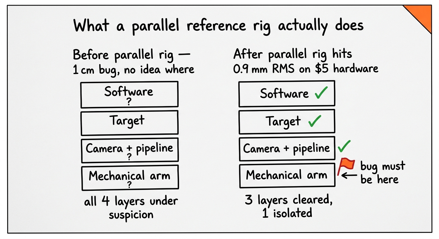
Now here is what that 0.9 mm number actually did — it shredded the China team’s suspect list.
I was running: a camera one resolution tier below theirs, a target whose geometric tolerance is four orders of magnitude looser, hardware costing roughly 1/100th of theirs. Same software. Same pipeline. Same pose-selection logic. 0.9 mm RMS.
If any of {software, pipeline, calibration target} actually had a bug, I would not be getting sub-millimeter. Period.
Software, target, pipeline: cleared.
So where was the 1 cm?
Process of elimination leaves one variable: the robot arm itself.
Specifically — calibration takes two inputs per pose: the camera’s measurement of where the target is, and the arm’s reported position of its own end-effector. If the arm’s report is wrong, the calibration matrix has to be wrong. Doesn’t matter what target you use.
We checked on site.
The arm’s zero point had drifted.
Not the target. Not the software. The mechanical zero of the arm. Re-zero the arm, re-run the same calibration on their gold-standard rig — error drops to 0.18 mm.
The expensive ball was always going to land on a kinematic chain that was lying to it.
Codifying it: the L2 direct RMS sentinel
After this one, I made the number itself a sentinel.
L2 direct RMS over a fixed pose set. Every time the line starts up. Every time the arm gets serviced. Every time it bumps into something. Every time the end-effector gets swapped. Run that fixed pose set first. Log the RMS.
Stable RMS → software, target, camera-pipeline all stable
RMS suddenly worse → suspect the arm first, software last
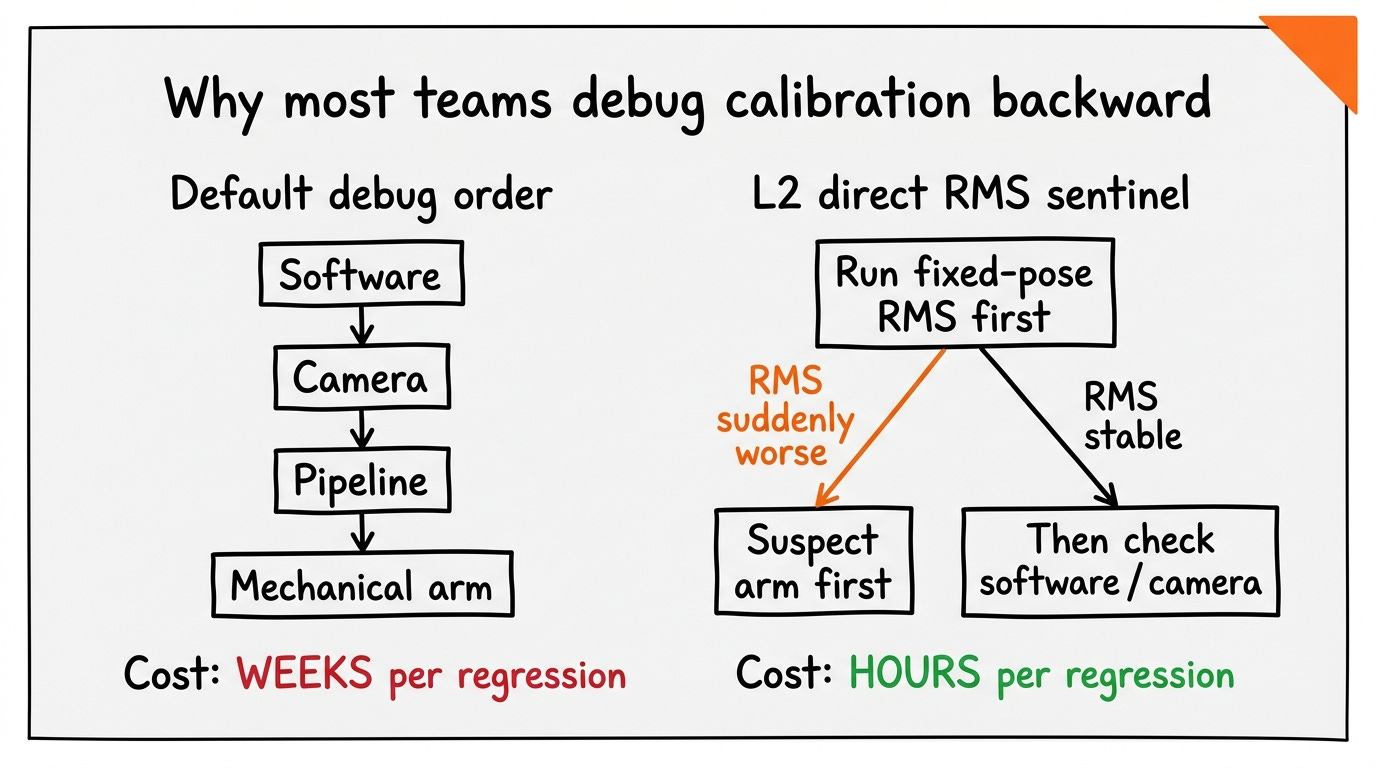
Most industrial-vision teams default-debug in the opposite order: software, then camera, then mechanical. That order costs weeks on every regression, not days.
A stable reference RMS lets you rule out the most expensive suspect first — and leave the cheap-but-changes-often software layer for the cases that actually demand it.
Shop-floor takeaway
When calibration drifts and you can’t find the bug, don’t debug on site. Reproduce the entire pipeline on a rig you fully control, with hardware as different from theirs as you can make it. That’s bisection.
The point of the parallel rig is not to match precision. It’s to eliminate every suspect of the form “if only the hardware were better.”
A fixed-pose L2 RMS will tell you the arm got bumped before any commit log will.
What you physically need: diffuse reflection, known geometry, sharp edges.
What you physically don’t need: a $30K invoice — or three weeks waiting for one.
*First Principles Manufacturing — physics, economics, and shop-floor reality from a nuclear-engineering PhD turned industrial-AI practitioner.
Great post and problem solving!